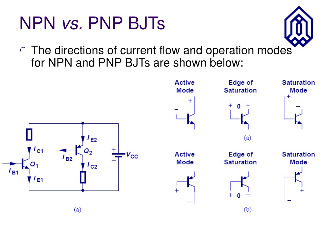
This is all about the NPN vs PNP transistors. In the NPN transistor symbol, the emitter terminal represents by the outward arrow. The symbolic structures of NPN and PNP are almost the same. It requires more time for switching operations as compared to the NPN transistor. It requires less time for switching operations as compared to the PNP transistor. It is used for low switching in electronic circuits or gadgets. It is used for fast switching in electronic circuits or gadgets. The PNP transistor is not much used as compare to the NPN transistor. The NPN transistor is widely used, due to the presence of electrons as the majority charge carriers. The PNP transistors are called ‘Sourcing sensors’. Sometimes, the NPN transistors are called ‘Sinking sensors’. low signal) connects to the base terminal of the PNP transistor, the PNP transistor is activated. high signal) connects to the base terminal of the NPN transistor, the NPN transistor is activated. The PNP requires a low signal at the base terminal. The NPN transistor requires a high signal at the base terminal. In the PNP transistor, current flows from the emitter (E) terminal to the collector (C) terminal. In the NPN transistor, current flows from the collector (C) terminal to the emitter (E) terminal. The minimum number of electrons is present. This transistor contains a large number of holes. This transistor contains a large number of electrons. The base terminal is made of N-type material. The base terminal is made of P-type material. The PNP transistor is a semiconductor device that consists of a single N-type layer and two P-type layers of semiconductor.įrom the N-type materials, emitter and collector terminals of the NPN transistor are formed.įrom the P-type materials, emitter, and collector terminals of the PNP transistor are formed. The NPN transistor is a semiconductor device that consists of a single P-type layer and two N-type layers of semiconductor. The PNP transistor stands for the ‘positive negative positive’ transistor. The NPN transistor stands for the ‘negative positive negative’ transistor. Similarities of NPN Transistor and PNP Transistorĭifference between NPN and PNP Transistors #.Difference between NPN and PNP Transistors.If you change PMOS M7 on NMOS transistor, the second stage no longer amplifies signal but serves as a voltage follower (R1 and C1 are no longer needed for compensation). Source: ("Preview" button in top right corner) For example in the following opamp design:

You may change PMOS on NMOS in designs, but a circuit won't work or it working principles will be different. Adding PNP to NPN or PMOS to NMOS ( CMOS) gives you more possibilities. You even have resistor–transistor logic and also transistor–transistor logic. If I remember correctly there is an opamp design done with only NMOS or NPN BJT and resistors done by Bob Widlar). Anyway, at the beginning of transitor history, for example opamps were build using only NPN BJT and resistors (see History of Semiconductor Engineering by Bo Lojek. repeatable Vth) NPN BJT and after that PNP BJT - but for that you need to dig more in the history. I assume that due to manufacturing problems the focus at the beginning was to manufacture good, reliable (e.g. That is, due to the fact that NMOS has the source on a lower potential than the gate to be turned on and PMOS has the source on a higher potential than the gate to be turned on: PMOS for pull-up and NMOS for pull-down due to the way there work. The same also applies to using NPNs and PNPs. It is a similar story for PMOS and pull down (you would need a -2 V supply). That can be done but is quite complex if you don't have that 7 V available. You would need 7 V at the gate to get 5 V at the output. you lose about 2 V (the 2 V is just an example, it can be as low as 0.3 V or as high as 5 V depending on the MOSFET you're using). In the right circuit the NMOS is operated as a source follower, the output "follows" the gate voltage with a (somewhat fixed) voltage drop.įor example, for a 5 V supply, the highest output voltage would be 3 V, i.e. In the left circuit the NMOS is operated as a switch (which is what you want). Without that higher voltage, shown in the right schematic, you cannot switch the NMOS on fully, the output voltage will be less than the supply voltage. Simulate this circuit – Schematic created using CircuitLab

When using an NMOS for pull-up, for the NMOS to be fully on, you would need a gate voltage that is higher than the supply voltage, see the left schematic:


 0 kommentar(er)
